Mechanical
Table of contents
Parts
Drivetrain
The Top End Pro Tennis Wheelchair was used as the base for the drivetrain. This was powered by two ODrive D6374 motors with a 1:20 gear reduction.
Wheelchair
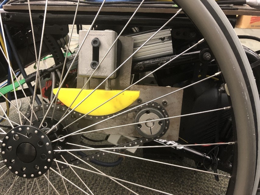
For the drivetrain mounting framework, attach two 19 cm double t-slot rails to the sides of the frame such that the rails are parallel to the wheels as shown below. These will be the mounting points for the motor and chain drive.
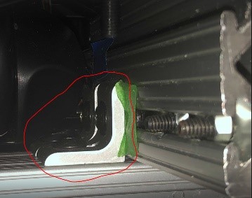
Attach one 44 cm double t-slot rail perpendicular to the installed 19 cm rails using corner slotted brackets as shown below.
Chain Drive
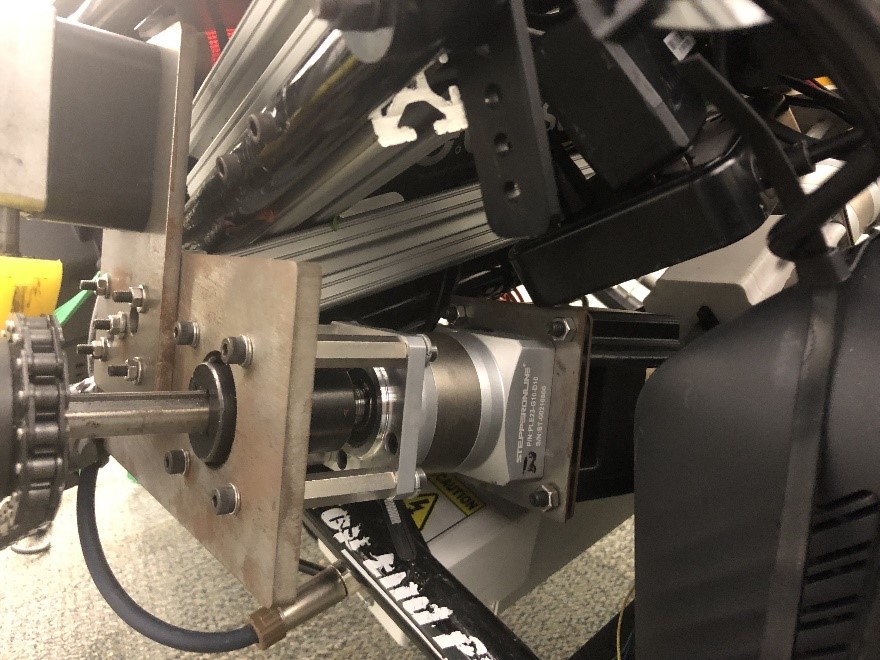
Assemble the motors with the 3D printed motor enclosures and motor enclosure plates. Attach the motor encoders and NEMA 23 1:10 gearbox to the output shaft of the motor using the NEMA 23 to 34 Adapter plate. This motor and gearbox assembly can be attached to the drivetrain frame using the waterjet drivetrain mounting plates using standoffs and keyed shaft couplers as shown below.
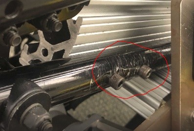
On the output shaft of the gearbox, loosely attach the small sprocket which will be tightened later during chain tensioning. Mount the machined large sprockets to the wheel of the drivetrain, and install chain around the wheel and motor sprockets. Tighten the motor sprocket so that the sprockets and chain are aligned. Finally, attach the tensioner and slide downwards onto the chain to remove slack. The final assembly can be seen below.
Manipulator
A HEAD Graphene Instinct Power tennis racket was attached to a 7-degree-of-freedom Barrett robot arm.
Barrett Arm
To attach the robot arm to the wheelchair, remove the cloth seat, handles, and backrest from the wheelchair. The steel waterjet seat plate can then be attached to the wheelchair and used as an anchor point for the robot arm.
End Effector
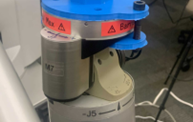
Attach the tennis racket to the end of the robot arm using two bolted 3D printed racket holders which sandwich the end of the manipulator as shown below.
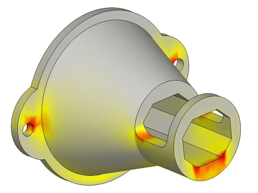
Since the racket holder is an area of high stress during a swing, a visualization of the possible failure points within the part was created. This can be seen below where red areas indicate high stress. Based on this analysis and initial testing, zip ties were used to secure and stabilize the racket to the racket holder.
Now check out the electrical page to see how to setup the electrical system.